Connecting LEDs
Single LED output
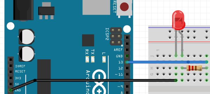
Assuming you have the default blink project running on the board, you can go ahead and plug an LED to the pin number 13 of your board to control it.
Beware of the LED polarity - cathode (-) has a bigger piece inside the LED, but a shorter leg; anode (+) has a smaller piece inside the LED, but a longer leg.
The resistor value you need to select using the Ohms law depending on current required by the LED. But typically you can use anything in the range of 200-500 ohm for Arduino’s 5V output level.
Multiple LEDs
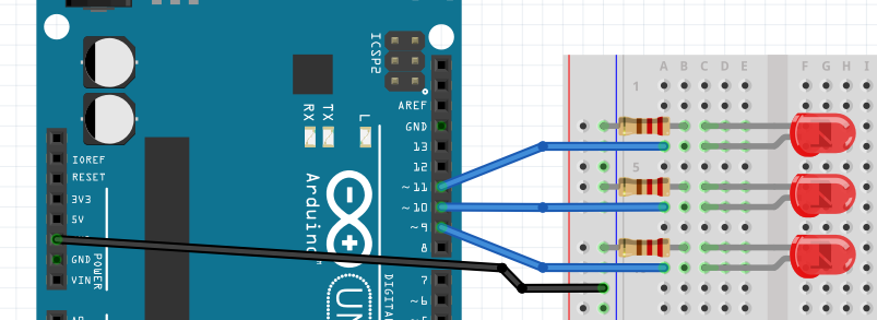
Now let’s try to connect three LEDs at the same time, using the bus bar for ground.
Pins 9, 10, 11 connect to the LEDs anodes, while all cathodes connect to ground bus via the resistors.
Modify the code to blink with all three LEDs.
#include <Arduino.h>
#define LED_PIN1 9
#define LED_PIN2 10
#define LED_PIN3 11
#define LED_BLINK_PERIOD 1000
void setup(){
  pinMode(LED_PIN1, OUTPUT);
  pinMode(LED_PIN2, OUTPUT);
  pinMode(LED_PIN3, OUTPUT);
}

void loop(){
  digitalWrite(LED_PIN1, HIGH);
  delay(LED_BLINK_PERIOD);
  digitalWrite(LED_PIN1, LOW);
  delay(LED_BLINK_PERIOD);

  digitalWrite(LED_PIN2, HIGH);
  delay(LED_BLINK_PERIOD);
  digitalWrite(LED_PIN2, LOW);
  delay(LED_BLINK_PERIOD);

  digitalWrite(LED_PIN3, HIGH);
  delay(LED_BLINK_PERIOD);
  digitalWrite(LED_PIN3, LOW);
  delay(LED_BLINK_PERIOD);
}
Build, upload and check if all three LEDs will bling consecutively.
Writing function to blink the LED
To avoid copy-pasting code, it is much wiser to use functions. Let’s try to write a simple function to handle a LED blink.
At the top of the code add a new function blinkLED that will return void and take a param uint8_t ledNo.
void blinkLED(uint8_t ledNo){
  digitalWrite(ledNo, HIGH);
  delay(LED_BLINK_PERIOD);
  digitalWrite(ledNo, LOW);
  delay(LED_BLINK_PERIOD);
}
Replace contents of loop to benefit from that function:
void loop(){
  blinkLED(LED_PIN1);
  blinkLED(LED_PIN2);
  blinkLED(LED_PIN3);
}
Build, upload, verify.
PWM output to control the brightness of an LED
The reason why we have selected pins 9, 10, 11 to connect the LEDs was that those pins support analogWrite, or more technically - Pulse Width Modulation - PWM output.
More details:
- https://www.arduino.cc/reference/en/language/functions/analog-io/analogwrite/
- https://www.arduino.cc/en/Tutorial/Foundations/PWM
To use PWM output the pin just needs to be configured as digital output, and then you can use
analogWrite(pin, value). Where thevalueis0-255brightness / pulse width.
Let’s try that:
void loop(){
  analogWrite(LED_PIN1, 50);
  delay(1000);
  analogWrite(LED_PIN1, 150);
  delay(1000);
  analogWrite(LED_PIN1, 250);
  delay(1000);
}
Build, upload & verify - the LED 1 should be blinking in three different level of brightness.
Fade in an LED
Now let’s try to write a function to fade-in an LED. Let’s use for loop for that.
void fadeIn(uint8_t ledNo){
  for(uint8_t i = 0; i < 255; i++){
    analogWrite(ledNo, i);
    delay(10);
  }
}
Test it out, calling this function from loop - the LED should fade in nicely over 2.5 seconds.
Similarly, you can also create a function to fadeOut in a similar manner.
void fadeIn(uint8_t ledNo){
  for(uint8_t i = 0; i < 255; i++){
    analogWrite(ledNo, 255-i);
    delay(10);
  }
}
You can also create a function that will do both depending on another parameter
void fadeInOrOut(bool fadeIn, uint8_t ledNo){
  for(uint8_t i = 0; i < 255; i++){
    if(fadeIn) analogWrite(ledNo, i);
    else analogWrite(ledNo, 255-i);
    delay(10);
  }
}
You can also replace the if with a shortened expression:
void fadeInOrOut(bool fadeIn, uint8_t ledNo){
  for(uint8_t i = 0; i < 255; i++){
    (fadeIn) ? analogWrite(ledNo, i) : analogWrite(ledNo, 255-i);
    delay(10);
  }
}
You can also add an option to set the fade animation length.
void fadeInOrOut(bool fadeIn, uint8_t ledNo, uint16_t lenInMs){
  uint16_t delayCycle = lenInMs/256;
  for(uint8_t i = 0; i < 255; i++){
    (fadeIn) ? analogWrite(ledNo, i) : analogWrite(ledNo, 255-i);
    delay(delayCycle);
  }
}
Beware that the above will be highly inaccurate due to the rounding.
For example lenInMs = 2500 (2.5 seconds) will effect in the cycle length 9ms, so the full animation will take 2304 ms.
To address that you can use delayMicroseconds as an alternative.
Keep out for the added .0 to the numbers. It indicates to the compiler that they should be treated as floating point numbers before being casted back into a non-
void fadeInOrOut(bool fadeIn, uint8_t ledNo, uint16_t lenInMs){
  uint16_t delayCycle = (len*1000.0)/256.0;
  for(uint8_t i = 0; i < 255; i++){
    (fadeIn) ? analogWrite(ledNo, i) : analogWrite(ledNo, 255-i);
    delayMicroseconds(delayCycle*10);
  }
}
In that case for the same 2500ms animation time you should get 9765us period, that will result in roughly 2499.84ms - the error is much lower.
Asynchronous control of LEDs
In the approach discussed above, any animation on the LEDs takes up all CPU ‘attention’, using delay or delayMicroseconds means that the MCU cannot do anything in that time.
If you have a solution that requires some process to be smooth (eg. motor control), but at the same time you would like to create LED animations, you can use simple async approach based on saving the current tick with millis()
It would look something like this - if you wanted to change standard blink to an async manner:
long lastBlinkChange = 0;
bool state = true;
void loop() {
  if( (lastBlinkChange + 1000) < millis() ){
    digitalWrite(LED_PIN, state);
    state = !state;
    lastBlinkChange = millis();
  }
}
Task: please try to use the same idea to control two separate LEDs in different periods.
Similarly to achieve smooth brightness transitions you could do:
long lastUpdate = 0;
bool state = true;
uint8_t currentBrightness = 0;
uint8_t expectedBrightness = 200;
void loop(){
  if( (lastUpdate + 10) < millis() ){
    if (currentBrightness < expectedBrightness){
      analogWrite(ledNo, currentBrightness++);
    }else if(currentBrightness > expectedBrightness){
      analogWrite(ledNo, currentBrightness--);
    }
    lastUpdate = millis();
  }
}
Next steps
Now let’s continue to work with digital & analog input