Connecting a button to digital input
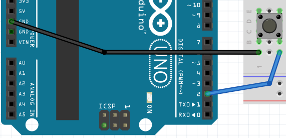
Let’s start with connecting a tact switch to GPIO number 2.
We will configure the input with an internal pull-up resistor, so the tact-switch should be connected between the GPIO and GND.
Try tu use following code, that:
- configures the button pin as a digital input with
INPUT_PULLUP, - in
loop()prints anUPorDOWNmessage based on the button input logic level every second.
#include <Arduino.h>
#define BUTTON_PIN 2
void setup() {
  pinMode(BUTTON_PIN, INPUT_PULLUP);
  Serial.begin(9600);
}

void loop() {
  if(digitalRead(BUTTON_PIN))
    Serial.println("UP");
  else
    Serial.println("DOWN");
  delay(1000);
}
Build, upload and observe. Note that digital level 1/true means that the button is not pressed, hence UP.
Handling the button press as an interrupt
Let’s try to achieve similar, but more robust and non-blocking behaviour using an interrupt.
#include <Arduino.h>
#define BUTTON_PIN 2
void setup() {
  pinMode(BUTTON_PIN, INPUT_PULLUP);
  attachInterrupt(digitalPinToInterrupt(BUTTON_PIN), handleBtnPress, FALLING);
  Serial.begin(9600);
}

void handleBtnPress(){
  Serial.println("button pressed");
}

void loop() {

}
TASK: Volume control with two buttons
Please use two buttons for an imaginary device volume control.
- configure two pins as interrupts
- attach two different functions to those interrupts (eg.
volumeUp()andvolumeDown()) - store the volume value in a variable with up to
10levels, - handle the button presses so the volume never gets below
0or more than10 - visualise the volume with a few LEDs (eg. 5) connected:
- either with just on/off
- or with PWM and nice fades between states.
When you finish leave the LEDs connected and the code as well.
Tips:
- you will need to check which other pins support interrupt on an ATMega328p, search for
attachInterrupton Arduino docs
Connecting a potentiometer
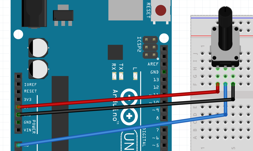
Now let’s try to connect a potentiometer. Typically a potentiometer is just a variable voltage divider - you need to connect the outer legs to voltage source and ground - to be able to use the middle connected to analog input.
Beware: depending on the board you are using, the maximum voltage could be different than 5V (eg. on ARM based 3.3V arduino boards).
Connect the potentiometer like this:
Let’s start off with the most basic code to handle the analog input
#include <Arduino.h>
#define POTENTIOMETER_PIN A0
void setup() {
  pinMode(POTENTIOMETER_PIN, INPUT);
  Serial.begin(9600);
}

void loop() {
  Serial.println(analogRead(POTENTIOMETER_PIN));
  delay(100);
}
Build, upload and observe the device output on the command line. You should see values from 0 to 1023 (as the analog input has 10 bit resolution).
TASK: analog volume control
Let’s try to use analog input to control the imagined volume level from the task above.
You can reuse the same code and LEDs as before, but rather than incrementing and decrementing the variable with button presses - poll the analogRead in loop and update the value.
A map(value, fromLow, fromHigh, toLow, toHigh) function could be useful to easily adapt from 0-1023 to something more useful.
Next steps
Afterwards let’s try to explore some more use of digital gpio