Using PWM to control a servo
You can use the PWM output, or more technically PPM (Pulse Position Modulation) - to control a servo.
Let’s start with connecting a servo:

We will use port 11, as typically we would use one of PWM-capable pins for servo control, there are alternatives though.
Starting code below:
#include <Arduino.h>
#include <Servo.h>

Servo myservo;
void setup(){
  myservo.attach(11);
}

void loop(){
  for(uint16_t i = 0; i <= 180 i++){
    myservo.write(i);
    delay(20);
  }
  for(uint16_t i = 180; i >= 0 i--){
    myservo.write(i);
    delay(20);
  }
  delay(1000);
}
Let’s try to build, and… whoops!
Most likely the code has failed to build due to unavailable libraries:
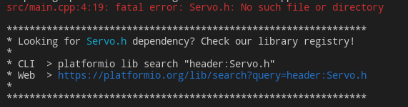
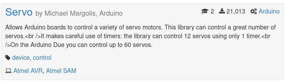
Luckily PlatformIO makes it ieasy for us to solve the issue, let’s try to do what they suggest and use the search on their website: https://platformio.org/lib/search?query=header:Servo.h.
Usually it’s worthy checking out most downloaded libraries first:
If you go to the “Installation” tab you should see the recommended way to add the library as a dependency to your project.
Let’s open up platformio.ini and add it:
Right under framework = arduino let’s paste the following:
lib_deps =
    arduino-libraries/Servo @ ^1.1.8
Let’s try again to build, upload and verify. Now the servo should be moving from 0 to 180 degress and then down from 180 to 0.
TASK: Servo action after a button press
Let’s try to build a simple logic with the servo that will:
- set up an interrupt for a button press
- move the servo quickly to 100 degrees
- hold for 3 seconds
- move the servo slowly to 140 degrees
- hold for 1 second
- move the servo quickly back to 0 degrees The imagined use case is that you are opening something up based on a button press.
Suggestions:
- if you just set the servo to given angle it’s reaction could be too dynamic, let’s try to use loops to make the movement with a manageable speed.
- rather than using three separate loops, you could write a single function that would move the servo from given angle to given angle, with a specific speed,
Using digital gpio to control a stepper motor
It is also possible to use plain digital GPIO to control a stepper motor via an external driver.
Please connect the stepper motor driver to the Arduino:
IN1- GPIO11IN2- GPIO10IN3- GPIO9IN4- GPIO85V-5VGND-GND
And let’s try the starting code:
#include <Arduino.h>
#include <Stepper.h>
const int stepsPerRev = 200;
Stepper myStepper(stepsPerRev, 8, 9, 10, 11);

void setup(){
  myStepper.setSpeed(50);
}

void loop(){
  myStepper.step(stepsPerRev / 100);
}
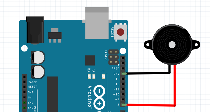
Using PWM to control a buzzer
PWM can also be used to generate simple, square wave tones and emit sounds with a buzzer.
You can just connect it to any of the PWM capable pins and ground:
Starting code would be as simple as this:
#include <Arduino.h>
#define BUZZER_PIN 9
void setup(){
  pinMode(BUZZER_PIN, OUTPUT);
}

void loop(){
  tone(BUZZER_PIN, 440, 100);
  delay(1000);
}
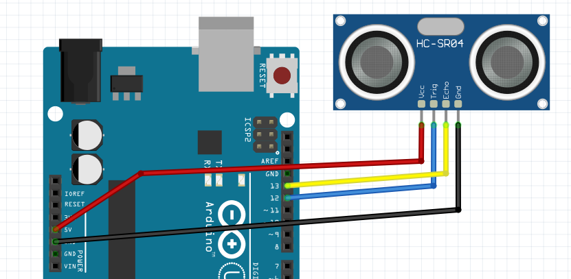
Ultrasonic distance measurement
Let’s try to use an ultrasonic distance measurement module. It works on a simple principle of sending and ultrasound signal and waiting for it to bounce back.
To connect it to your board you need to attach power (5V & GND) and two digital signals - TRIG and ECHO. Any digital pins can be used.
Example wiring on a diagram:
To work with the sensor you will need a proper library. A quick search on platformio would bring up: https://platformio.org/lib/show/1507/Ultrasonic
Let’s try to add that library to your project (edit platformio.ini) and try a basic example.
#include <Arduino.h>
#include <Ultrasonic.h>

Ultrasonic ultrasonic(12, 13);

void setup() {
  Serial.begin(9600);
  ultrasonic.setTimeout(40000UL);
}

void loop() {
  Serial.print("Distance [cm]: ");
  Serial.println(ultrasonic.read());
  delay(1000);
}
Let’s try to build, upload & verify the serial output.
TASK: Lowering the sensor timeout for robustness
Important note - observe what happens when there is nothing in front of the sensor - how long it takes for the code to timeout practically blocking the code from moving with any other work.
If you have an use-case that doesn’t really require full sensor range (typically up to 200cm), but you only care if there is something close to the sensor - you can address that issue setting the timeout lower.
Let’s try to modify
TASK: build a complete parking sensor solution
Now you should have all the tools required to build a fully functional parking sensor.
Let’s try to implement the following:
- ultrasonic sensor with distance measurement in the range of 0-50cm
- a few LEDs displaying the measured distance
- buzzer that will change its tone and period between beeps when the object gets closer
Next steps
Now let’s continue to work with digital I2C bus and an OLED screen